Email:


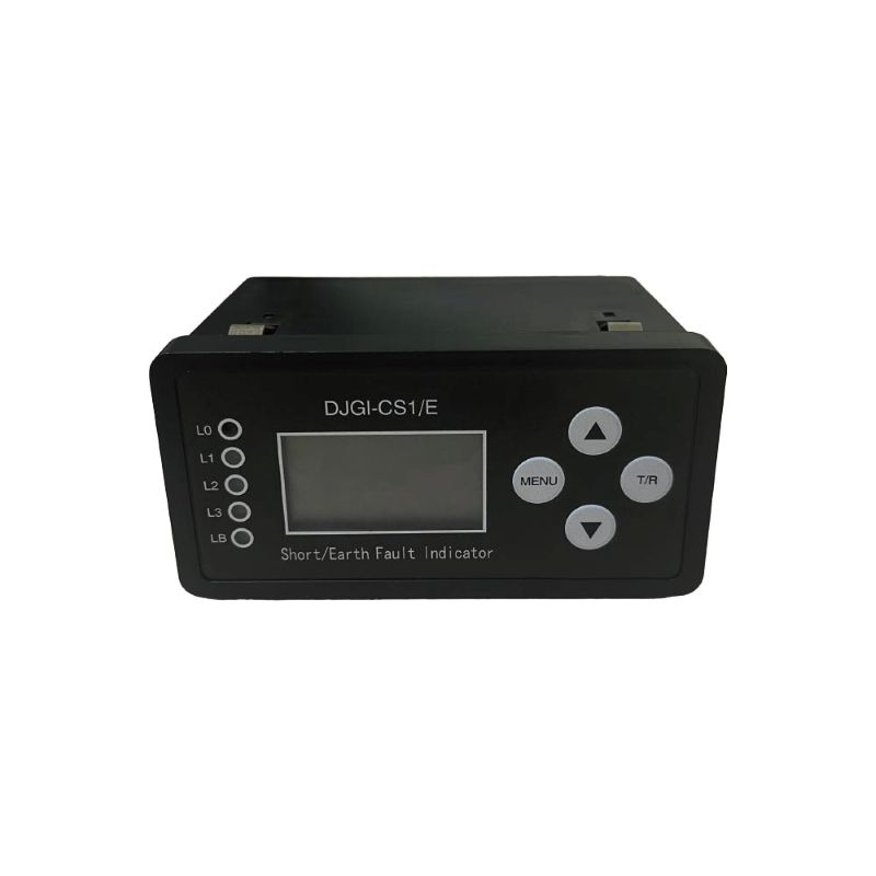
Procedure For Fitting Fault Passage Indicators On 33kV Conductors Hot Stick Method
APPROVED TOOLS Approved tools and equipment to carry out this procedure are as follows: 1 8ft Grip-all Clampstick 1 8ft Universal Stick with attached mirror 1 8ft Universal Stick Rotary Prong 1 8ft Wire holding Stick (All Short Sticks used to carry out this procedure shall have red marker tape 0.8mtr from top)
HOT STICK PROCEDURE CARRIED OUT FROM AN I.A.D. Before commencing refer to 5.2 section 4.3 of the PSLWM Carry out a visual inspection both spans either side of work position. Carry out a mirror inspection of the insulators, binders etc. to ensure their integrity. Attach the wire holding stick to the centre phase conductor 2 metres from the pole on the side being worked on. This will enable the linesman to maintain the required safety clearance from the conductor while working away from the pole. Working below the red marker band on the wire holding stick, work can now commence fitting the CHK LT40 to the phase conductors.
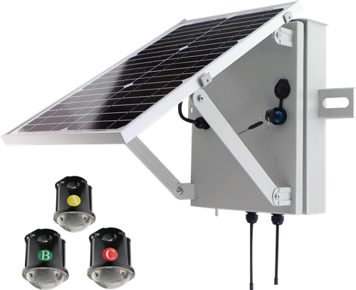
Installation of Units As per training instruction There is one unit per phase. Establish phasing at point of installation. Assign one unit to each phase. Check and note the unit Identity. Check the unit is switched on and operating. The first unit to be installed has the solar panel facing as near to due south as possible. Locate the unit in the Grip-all clampstick head. Open the current transformer and spring-loaded fingers. Apply to the overhead conductors and check security of mounting. Disengage Grip-all clampstick.
Check the operational indicators to verify the units are switched on and sensing. Check via transceiver and Toughbook PC that solar charger is operational, battery is charging and unit is measuring load current. Remove the wire holding stick from the conductor. Remove the red marker band.
Removal of Units Connect the Grip-all clampstick to the FPI adapter. Do not try to pull the FPI vertically down to disconnect. With the Grip-all clampstick vertical pull the stick towards the pole in line with the conductor. The unit will then disengage from the conductor. Remove the unit from the Grip-all clampstick. Switch the unit off. Remove red marker band
Hot Stick Procedure Carried out from a Pole Before commencing refer to 5.2 section 4.3 of the PSLWM Carry out a visual inspection on both spans either side of work position. Test the crossarm with an approved running earth. Ensure the earth spike is a minimum of 3metres away, and installed to the right or left side of the testing linesman. (Only one linesman should be between the pole and the earth spike whilst testing is being carried out) Mark the pole 0.8 metres down from the lowest Live conductor with a red markerband. Carry out a mirror inspection of the insulators, binders etc. to ensure their integrity. Carry out installation as per 3. of this procedure. Removal as per 4. of this procedure