What Does A CT (Current Transformer) Do In An Electrical Distribution Board?
As noted by others, a current transformer is intended to facilitate measurement of large currents. Usually the transformer is just a secondary winding with an open core. A low resistance "burden" resistor may be connected across the secondary winding and the voltage across it measured to determine the current. Note that the current transformer will try to make on its secondary winding whatever voltage is needed to push the correct current through the burden resistor so the burden resistor is chosen such that the maximum monitored current will produce a manageable voltage across the secondary. For example, a current transformer with a 100:1 ratio, monitoring 100 amperes, wants to push 1 ampere out of its secondary. If it is burdened with a one-ohm resistor, this will produce 1 volt on the secondary across the burden resistor, which can easily be monitored with simple meters.
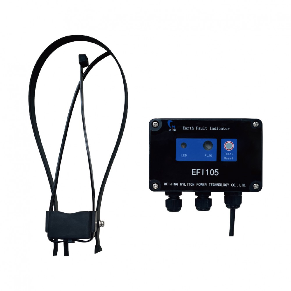
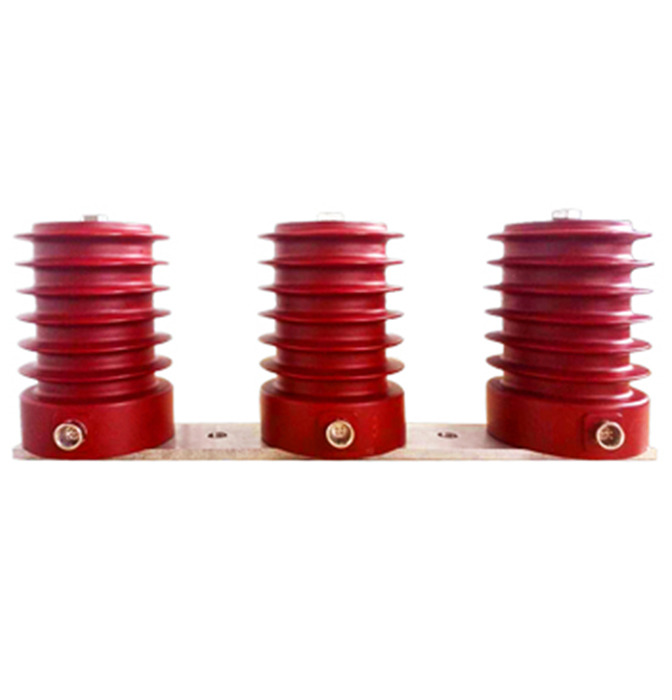
The line to be monitored is passed through the center of the core of the current transformer, acting like a one-turn primary. The core may be designed as a split circle so that it can be clamped around the monitored wire without having to break or disconnect the wire.
Also, a current transformer allows the line current to be measured with ordinary meters or sense relays without subjecting them to the high voltages present on the monitored lines. There is sufficient insulation in the covering of the monitored wire together with the insulation of the current transformer to allow the monitored (secondary) winding may be sensed using instruments which are referenced to local neutral or earth ground.
 Email:


