Want to book by phone? Call usTel: +86 189 0119 4516 Email: overseas@hyliton.com
Email: overseas@hyliton.com Email: overseas@hyliton.com 


Beijing Hyliton Power Technology Co.,Ltd.
Address:6th floor of Tower B, Advanced Material Building, Yongfeng Industrial Base, Haidian Dist., Beijing, 100094 China.
Contact: Ms. Sarah Wang
Tel: +86 189 0119 4516
Mobile phone: +86 10 5871 1928 ext. 1759
Fax: +86 10 5871 1938
E-mail:overseas@hyliton.com


Introduction Of On - Line Monitoring System For Line1. Single System Basic ConfigurationOverhea···
Overhead communication fault indicator Several Groups (3 / Group)
Overhead communication terminal Several Units (each communication
terminal may equipped with 1-3
Groups of fault indicators)
Asymmetrical current source Several Units (optional)
Information processing terminal 1 Set
Computer (Central Station) 1 Set
Central station software(regional 1 Set
master station is optional)
Installation tools Assigned according to standard
(1 Set/100pcs)
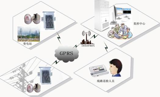
Line fault on-line monitoring system is a set of intelligent fault management system with remote distribution monitoring, centralized management and instant notification. It makes the existing fault detection technology progressed, which combines the line fault detection and communication transmission technology. By sending the information to the master station and completing the topology fault location, display and alarm notification at the master station, the fault location and query of the line become much faster. As shown below, the system consists of communication fault indicator, signal source, communication terminal, working master station,etc. And the working master station includes signal receiving terminal, master software, computers and mobile phones.

The communication fault indicator is mounted on the line, which is mainly composed of modules of fault detection, current sampling, triggering alarm, wireless radio frequency communication, power and other functional modules. The main function is to detect the line information of power transmission, power outage, earthing, short circuit, etc., and transfer them to the communication terminal through short-range radio frequency communication. Three fault indicators are one group, which can be installed and removed while line is in charge condition using special installation tools.
The fault indicator is usually in the power-saving sleep state; when the line state changes, the detection function module will be activated and it will analyze, calculate and process the collected information by the SCM, to determine whether the line occurs state changes such as power transmission, power outage, short circuit and earthing; If the changes are determined,the alarm function module would be activated and the information would be transferred securely and accurately through the radio frequency transmitting module. After receiving the information, the communication terminal returns a "received" signal, and the fault indicator returns to the sleep state after receiving this signal.
The communication fault indicator adopts a double power supply mode using line powering as its main power, lithium batteries and super capacitors as a backup power supply. The device uses line powering supply when it is in normal condition, and charge for the backup power supply;when the line power is out, or the power supply is not sufficient, the super capacitor start to supply power; when the super capacitor power is depleted, the backup battery starts to supply power and it can supply more than 8 years.
The Communication terminal is mainly composed of the MCU processing unit, GSM / GPRS remote communication, short-range radio frequency communication and photovoltaic power supply processing and other functional modules. Main function: two-way radio communication with the fault indicator to complete the interaction of information, including the configuration of indicator parameters, control and receiving the fault information of indicators; complete communication with the master station through the means of GSM / GPRS and so on, which includes receiving the command of master station, control and reporting various operating information and detected information of the indicator and terminal upwards automatically. The terminal should be installed on the pole which is less than 100 meters from the communication fault indicator , using hoop to fix directly.
Each communication terminal can be equipped with multiple sets of communication fault indicators in the range of 100 meters.
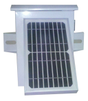
Communication terminal adopts a dual power supply mode, using solar energy as the main power, rechargeable batteries and super capacitors as a backup power supply. In a clear day, the solar panels can provide sufficient energy, while the back-up power can get charged; When at night and cloudy day, the communication terminal is powered by backup power supply.
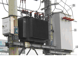
The signal source is installed at the neutral point of the earthing transformer of substation (connected to the bus / outlet when there is no neutral point). Signal injection method to detect earth fault requires the signal source going into automatic, short-term dynamic resistive load, generating a special zero sequence current signal (less than 50A) between the substation and site earthing point, and resulting in encoded signal current superimposed on the load current through the coding control of the resistance in case of earthing fault occurred in the system. The earth fault indicator installed at the point of substation outlet and branching of line will detect this current signal and indicate it.
The primary part of signal source device, which is applied in neutral point earthing system by arc suppression coil, is connected to the neutral point of earthing transformer. And the primary part of signal source, which is applied in Neutral point unearthing system, is connected to the three-phase bus / outlet. When the earth fault occurs on the line, the substation signal source determines the earth phase automatically by detecting the bus zero sequence voltage and the three-phase voltage. When the earth fault continues for a period of time, the signal source would go into the AC contactor of the corresponding phase and starts to send the current signal sequence, there’s no signal get through in non-faulted outlet and non-faulted phases. After the signal source sending out the signal, the fault indicator installed on faulty phase of the faulty line detects the current signal sequence from the signal source, then flop, flashes and transmits the action signal to the master station through the communication terminal.
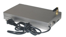
The information processing terminal performs the following functions: communicating with the communication terminal and performing protocol conversion, extracting the information from the communication terminal or forwarding the background information to the communication terminal; communicating with the background, forwarding the information to the communication terminal or forwarding the information from the communication terminal to the background; When the master station completes the fault judgment, and needs to send the fault information through SMS for alarm, it will send the information to the set mobile phone through the mobile communication network, so that the relevant staff can deal with the line fault in time.
Computer specific configuration requirements:
Server: Intel Pentium CPU 2.6G or above, 4G memory above, hard drive 160G above, at least one serial interface (COM1 port) and USB port;
Operating System: 2003, 2008 Standard Edition or Enterprise Edition;
Monitor;
Keyboard / mouse / optical drive / multihole socket;
The software of master station mainly consists of three parts: system management (area management, user management), application platform (general information query, alarm information query, SMS information query) and device management.
Specific parameters are as follows:
No. | Main functions | Access rights | Brief description |
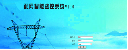
1 | Intelligent monitoring system starts | All users | Open relevant functions of the CS part and run; Click to enter the home page, start the default browser, enter the BS page. |
2 | Login interface | All users | 1)Root users, with all the permissions to view, modify all the functions of software; 2)Regional users, with regional permissions to view, modify the regional functions of software; 3)Subsidiary regional users, only with the permissions to view the software functions of the associated lines in their region. |
3 | Regional management | Root users | The regional user name, password, and region name are added by root |
4 | User management | Root or regional users assigned by root
| The regional users assigned by root manage the subsidiary users, including add users, passwords, telephones, and associated lines in their respective regions. |
5
| Common information query window | All users
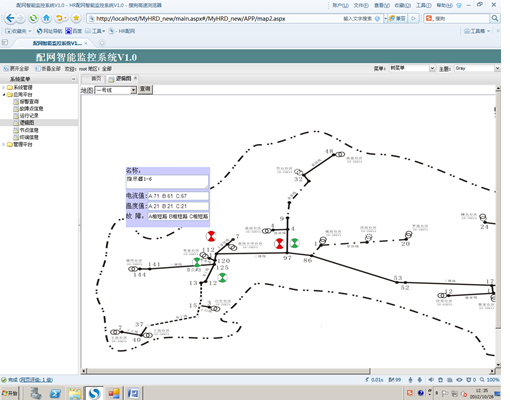
| Logic diagram 1) The edit rights for the logic diagram are of regional users or root 2) The query rights for the logic diagram are of all users 3) function A) The left side of the logic diagram adopts a four-level tree structure in accordance with the region, line, branch line, branch, branch of the branch B) Click one item on the left side of the tree structure, the right side can automatically invoke the respective logic diagram C) can quickly search for a point, bring up the respective logic diagram, click on one point of the logic diagram, the branch point of left tree automatically refresh to the corresponding point D) some point information on the logic diagram real-time display of the current data brought up from the database, it would flash if it’s in fault status |
All users | Current query: three-phase parallel display of data, curve chart display, you can export excel | ||
All users | Temperature query: three-phase parallel display of data, curve chart display, you can export excel | ||
All users | The earth electric query: three-phase parallel display of data, curve chart display, can be exported excel | ||
All users | Three indicators battery parallel display data, curve chart display, you can export excel | ||
All users | Terminal battery voltage, solar charging voltage, whether is online | ||
Alarm information query window | All users | 1) After the software is logged in, the information will be automatically scrolled 2) You can also query the alarm information for a period of time 3) Click the alarm information, the logic diagram can automatically jump to the alarm point | |
6 | Equipment maintenance | Root or regional users | Query, edit the related information of the field devices, including the upper node of the indicator, the belonging terminal, the group indicator of the belonging terminal, the belonging line; the link address and belonging line of the terminal,etc. |
7 | SMS information query | All users | Query for sent SMS and received SMS in a period of time |
After the information processing terminal receives the data of the communication terminal installed near the fault point, it performs protocol conversion on the data, extracts the application data and sends it to the background for analyzing and processing. After a failure is determined, the software of master station show the fault station name, line name, alarm time on the chart, flash on the line map for alarming, and notify the staff on duty by SMS at the same time.
The software has the function of comprehensive judgment. When the line occurs fault, the lines under the same bus segment of the same transformer will all have reaction,it makes the comprehensive judgment in the main station through the reaction situation between each line as well as between each phase of the same line, which can improve the stability of fault detection; the software supports distributed database, can search for history record; it also supports B / S structure (Browser / Server), which gathered the core parts of system realization functions on the server. As long as a browser is installed in the client’s computer, they could access the information on the server through the browser; the software work interface is a set of intelligent management system which is humanized, easy to learn, and easy to maintain.
The initial interface is: 4.2.3 Master system
An important component of the distribution master station is the WEB release module, which mainly provides the system operation situations for the users, including the configuration of relevant equipment by the maintenance personnel, and view of status of each line by users, etc.
This WEB release interface for the system is MySQl5.0 database. All the data input, output and so on are saved to the database, using B / S structure, and the user access to view through the browser.
System monitoring and alarm principle: When the line occurs short circuit, earthing, power outage, power transmission and other operating status changes, the fault indicator would have detected the changing signals, and would transfer them to the communication terminal through the short-range RF signals; and then send the message to the working master station
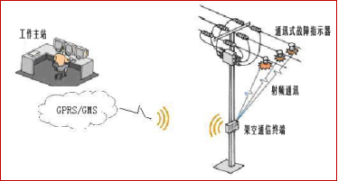
through GSM / GPRS via the communication terminal. The master station computer flashes visual display fault section through the line color changes; it pop-up dialog box for alarming at the same time; and send fault information in the form of short messages to the inspector mobile phone.

Download the specifications of SPI-2000 Overhead 2-Remotes Fault Detection System Transformers
Previous: no more
Next: no more

Copyright Beijing Hyliton Power Technology Co.,Ltd. All rights reserved.

Beijing Hyliton Power Technology Co.,Ltd.